Exhaust Gas System
(1) Three chamber: Analysis Chamber (Anal), Preparation Chamber (Prep), Load-Lock Chamber (LL) ( or Fast Entry).
- LL is a small room with a Fast Entry Door for samples and tips, Exhaust gas by TMP1-RP2, the vacuum level is measured by a BA.
- Prep is a large room for sample cleaning, deposition and LEED/AES measurements, with TMP2-TMP3-RP3 and a TGP2 pumping, and an ion gauge (UHV2) measuring the vacuum level.
- Anal is a large room with STM and cryostat and an IP1 pumping out. There is also a TGP1. The vacuum level is measured with an ion gauge (UHV1).
- The Ar gas line for Ar+ sputtering is connected to Prep through the VLV1. The gas inlet line can be evacuated by TMP1 through V14.
(2) TMP2, TMP3, V5, V6, V7, V9, V11 operate from the interlock system.
(3) TMP1 is manual. Operate SET+START, SET+STOP.
(4) The TMP2 switch is easy to chattering. To completely turn off LEVITATION after stopping, remove the knob on the rear panel of the controller.
(5) GV1 is manual, but the interlock GV1 is swithced off during baking.
(6) BA, UHV1, and UHV2 gauge may indicate that one gauge is ON or OFF, depending on whether there is leakage current.
Lock-in Amplifier
We employ EG&G 5209 Single Phase Lock-In Amplifier. If you interest in this meachanism, plz refer to this website (https://www.atecorp.com/products/eg-g/5209) and you can download manual for free.
1. Converst the Lock-in Amp output to differential conductance
The tunnel current It be expressed as a function of bias voltage Vb.*1 With a small bias modulation vcoswt,

Here the differential conductance is set as G=dI/dV. Since v is the amplitude, it is √2 times the effecive value ve. This signal is amplified by a preamplifier and enters a lock-in amplifier. Ideally, only the components of coswt are extracted and the size of G・v can be measured.
Assume that preamp gain is g and the sensitivity of a lock-in amplifier is s. At this point, the signal of effective values is output at 10V. The output of the lock-in amplifier,

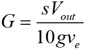
It can be converted to differential conductance. For Omicron preamps, g is usually 3×10⁹ V/A. When the freuency band is set to be large, it becomes 3×10⁷ V/A. In the current Nanonis system, the ooutput of the preamplifier is entered into the Input1 pin of SC4. Output the signal converted to 1 V/nA is Output from the 3 pins, which is fed into the input scope and the lock-in amplifier. So, we can assume that g=109. For example, when ve=10mVrms, s=100mV, s/(10gve)=10-9 S/V, so 1V output from the lock-in amplifier corresponds to 1ns.
2. Phase Adjustment
STM tunnel junctions have capacitance components C in addition to resistance component R=1/G. If the resistance of the conductor is sufficiently small conpared to R or 1/(wC), then the equivalent circuit is a parallel circuit of R and C. If the complex impedance is Z,
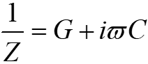
So, to correctly measure G, one must not only look at the amplitude of the output of the lock-in amplifier, but also adjust the phase appropriately to see the cos component.
The phase of adjustment of the lock-in amplifier is done as follows. C is the capacitance between the whole tip and the sample plat, and does not change when the tip is withdraw. So, withdraw the tip, apply bias modulation of appropriate size (~10 mV) after making the G compoenent of the above equation to zero, and turn the phase offset knob so that the cos component of the output of the lock-in amplifier is zero. When the frequency w of the bias modulation is changed, or when the tip or sample is changed (C is changed), the phase must be adjusted in this way.
3. Determine the Frequency of Bias Modulation
When the signal is amplified the preamplifier, a low-pass filter is applied. The frequency of the modulation applied to the bias must be lower than the frequecy of the low-pass filter. The Omicron preamp we currently use in the basement room is 800Hz, so it must be smaller than that. Since the controller of Nanonis reads the value at 10kHz, the delay should be fine. Lock-in amp are supported to 120 KHz. If it’s later than that, there’s no problem.
Select the frenquency with less noise when viewed with a spectrum analyzer that is not a multiple of 50 Hz. In eastern Japan, a multiple of 50 Hz may include electrical noise, so it is better not to use it as a multiple of 50 Hz. The preson who wrote the highest possible frequency was using 496 Hz.
4. Determine the Amplitude of Bias Modulation
Ideally, it is as good as or smaller than the kBT.
If it is LHe Temp (4.2K=0.36 meV), we should set it to 0.5-1nV but we may make it larger depending on the S/N condition. If the interve between the biases being measured is large, the modulation may be increased accordingly (for example, when measuring at 10 mV intervals, the modualtion may be 10 mV).
At LN2 Temp (77 K=6.6meV), it should be 10mV.
5. Determine measurement parameters
In the analog lock-in amplifier, the measured signal is multiplied by the reference signal (frequency omega square wave), and the output is smoothed with a low-pass filter to extract the Omega component of the measured signal. For the time change of the measured signal, the change of the output is delayed by the time constant T of the low-pass filter. Measurement parameters must be set with this in mind.
On EG&G 5209, the low-pass filter can be switched between 1 stage (6 dB/OCT) and 2 stage (12 dB/OCT). The latter has a higher frequency of attenuation (which can suppress high-frequency noise), but has a longer response time.
As a rule of thumb, wait 5 to 6 times the time constant t of the low-pass filter from the bias change to the start of te measurement. The Settling Time of t=20ns for the Time constant t=25ms. If the Setting Time is appropriate, sweep the bias back and forth. It is necessary to confirm that the spectrum obtained does not deviate in the direction of bias in the round trip.
6. Interpretation of Measurement Results
The differential condutance measured in the STS is said to be “proportional” to the LDOS. But, since the proportional constant can be location-dependent, we must take care when measuring spatial changes in the differential conductance.
Suppose that It is given as follows, considering that the “tunnel matrix model” can be applied to the tunnel junction of STM,

where x, y and z are tip position, M is the matrix element, and p is the LDOS. Assume that M can be taken out of integration, independent of the momentum k or energy E of the electron, and that the z-dependence of p can be separated as exp(-kz)p(x, y, E),
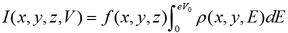
where we impose all the matrix elements and other complex quantities into the function f. In the constant current mode of STM, the bias voltage is set to an appropriate value V. Adjust z so that the tunnel current becomes the value I0 of the set point. If z in this case is z0,

the relationship is established. So,

The differentail condictivity G measured in a lock-in amp is the partial derivative of I(x, y, z0, V) with respect to V. In other words.
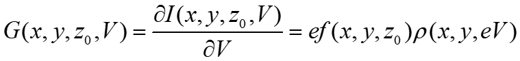
And this is

This equation means that the measured differential conductance G is “standardized” by the integral
of LDOS and the “standardized factor” is generally location-dependent.
So, the spatial change of the measurement G is not necessarily the spatial change of the LDOS. In particular, if the spatial change is independent of energy, it is possible to observe the spatial change of the “normalizer”. Also, if conductance mapping is perfomred by recording the output of the lock-in amp while scanning at a low speed, rather than measuring the tunneal spectrum at each point, changing Vb also changes the “standardization factor”.
